Helix World +
Theory of electric and magnetic field in electromagnetic waves
1 Electromagnetic waves have no electric field − 日本語 − <Reference 王様は裸>
2 Unclear about radio waves − 日本語 −
3 Form of current − 日本語 − <Reference Comment>
4 Electrical and Magnetic forces − 日本語 −
5 Electromagnetic waves are traveling magnetic fields − 日本語 −
6 Generate electromagnetic waves − 日本語 −
7 Receive electromagnetic waves − 日本語 −
8 Polarization − 日本語 −
9 Insertion device for synchrotron − 日本語 −
10 Longitudinal and Transverse Waves − 日本語 −
11 Vibration of string − 日本語 −
Nov./15/2024
< 1 Electrical and Magnetic Forces >
Table 1 shows the forces acting on electricity and the forces acting on magnetism, comparing attraction and repulsion.
The attraction and repulsion between the two magnetic fluxes as shown in Table D corresponds to the attraction and repulsion between the two electric currents as shown in Table C. And the attraction and repulsion acting on the N and S poles of the magnetism, as shown in Table B, correspond to the attraction and repulsion acting on the positive and negative poles of the electricity, as shown in Table A.
It is easy to infer the attraction and repulsion forces acting on the two magnetic fluxes, as shown in Table D. Because the behavior of electricity and magnetism is very similar.
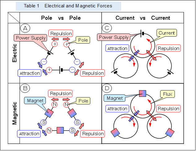 |
Note that in electricity, current can flow without leakage because there are conductors with small electrical resistance and insulators with large electrical resistance. Thus, the forces shown in Table C are clearly apparent.
However, magnetic materials do not have a material with a large ratio of resistance like the conductor and insulator of electrical materials, and leakage is high, so a clear path cannot be formed. Thus, the forces shown in Table D are still ambiguous.
< 2 Current converted to magnetic field >
Figures 1 and 2 show schematically how a current (electrical energy) passing through a conductor is converted into a magnetic field (magnetic energy) like that of a permanent magnet, and decreases.
Figure 1 shows a pulse current through a conductor before it passes through a ring-shaped magnetic core. Figure 2 shows the current after it has passed through, when the magnetic core is magnetized with large hysteresis, as in the case of a hard ferrite or permanent magnet.
Figure 3 shows, for example, when the magnetic core is not magnetized like soft ferrite without loss due to hysteresis.
 |
When a pulsed current passes through a magnetic core, the current is limited and some of it passes through. The shape of the passed pulse is changed. And the rest of the restricted current is reflected back toward the power supply.
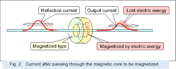 |
As shown in Figure 2, when a pulsed current enters the magnetic core as it passes through the magnetizing magnetic core, the first half of the pulsed current is stored in the magnetic core as magnetic energy (a portion of the passing current magnetizes the magnetic core and makes it a permanent magnet).The magnetic core, which has become a permanent magnet, does not release any magnetic energy into the passing current, and the passing current pulse has a lower wave height and reduced electrical energy.
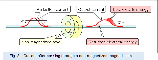 |
As shown in Figure 3, when a pulsed current passes through a non-magnetized magnetic core, part of the electrical energy is stored in the magnetic core as magnetic energy when it enters the magnetic core, and when it exits the magnetic core, the stored magnetic energy is added to the pulsed current as released electrical energy.
As a result, the passing current pulse has an extended wave width and a lower wave height, but the electrical energy is maintained.
< 3 Current through various conductors >
Figures 4 through 11 show conceptually the current profiles formed by the magnetic fields generated by oneself in the various conductors.
Figure 4 shows the current and magnetic field passing through a cylindrical (bar) conductor and the current profile.
A direct current in a conductor generates an outer magnetic flux outside the current (due to Ampere's law), and that outer magnetic field exerts a force (due to Lorentz force) that moves the current toward the center, so that more current passes through the center of the conductor.
An alternating current in the conductor causes the outer magnetic field to generate eddy currents. The eddy current pushes the current outward, and the current in the outer edge increases. As the current moves to the outer edge and the current in the center decreases, a central magnetic flux, whose polarity is reversed from the outer magnetic flux, is generated in the inside of the current. The central circumferential magnetic flux then generates a force (Lorentz force) that moves the current outward, and the current concentrates on the outer edge of the conductor.
--- Epidermal effects (Skin effects) appear.
Note that when the alternating current is concentrated in the outer edge of the conductor, the eddy currents generated for the central flux cannot pass through the outer edge, i.e., the outside of the conductor, so that sufficient eddy currents corresponding to the central flux are not generated.
Therefore, the force generated by eddy currents against the current is stronger in the outward pushing force than inward pushing force. If the frequency becomes higher, it becomes more pronounced, and the passing current is further concentrated in the outer edge. And at even higher frequencies, the current will eventually become more difficult to pass.
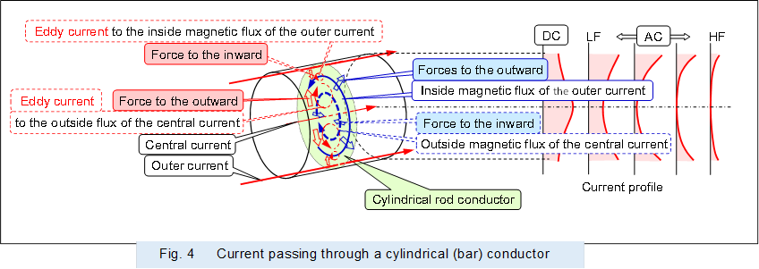 |
Figure 5 shows the current and magnetic field passing through a cylindrical (bar) conductor with high electrical resistance, and the current profile.
If eddy current effects are limited by the resistance, more current will pass through the center of the conductor, just like direct current, even if a high-frequency alternating current is passed through the conductor with high electrical resistance.
--- Middle bone effects appear.
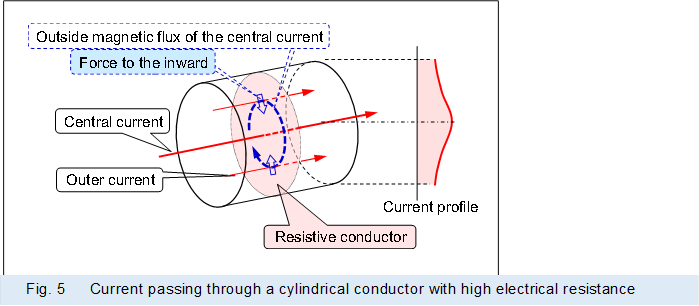 |
Figure 6 shows the current and magnetic field passing through a cylindrical (pipe or tube) conductor and the current profile.
When DC current is supplied, more current passes through the inner wall side of the cylindrical (pipe, tube) conductor, and when alternating current is supplied, more current passes through the outer wall side of the cylindrical (pipe, tube) conductor.
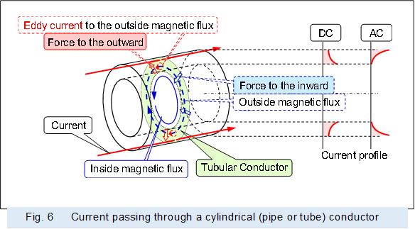 |
Figure 7 shows the current and magnetic field passing through a pair of reciprocating coaxial cables in which the central conductor is covered by a cylindrical (pipe, tube) outer conductor, and the current profile.
A synthesized magnetic field is formed in the coaxial cable from the magnetic field generated by the center conductor and the magnetic field generated by the outer conductor. When direct current is supplied, more current passes to the outer wall of the outer conductor, and when alternating current is supplied, more current passes to the inner wall of the outer conductor.
--- Proximity effects appear.
 |
Figure 8 shows the current and magnetic field passing through a circular waveguide and the current profile.
The circular waveguide consists of a pair of reciprocating coaxial cables with the center conductor omitted, and a magnetic field like that of a coaxial cable exists in it. When a high frequency alternating current is supplied, more current passes through the inner wall side of the conductor.
 |
Figure 9 shows the current and magnetic field passing through a plate conductor and the current profile.
As in the cylindrical (bar) conductor in Figure 1, the outer magnetic flux generated a force that moves itself to the center and eddy currents that move itself outward. When direct current is supplied, more current passes through the center of the plate conductor, and when alternating current is supplied, more current passes through the area away from the center of the plate conductor.
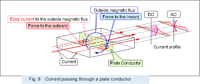 |
Figure 10 shows the current and magnetic field passing through a pair of opposed plate conductors, such as the main part of a rectangular waveguide, and the current profile.
A synthetic magnetic field is formed in the conductor by the magnetic fields generated by the going and returning plate conductors. Corresponding to this synthetic magnetic field, the current passing through each plate conductor passes through the area away from the center when the direct current is supplied, when alternating current is supplied, more current passes through the center of the conductor.
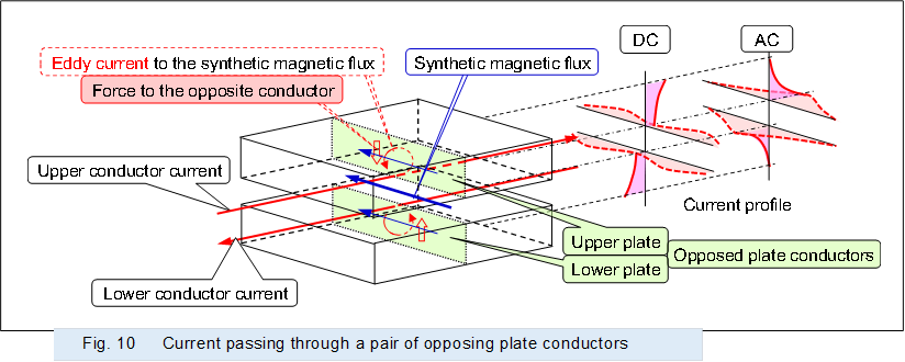 |
Figure 11 shows the current and magnetic field passing through a pair of opposing conductors with a ridge in the center of the opposing surface in Figure 10 above, such as the main part of a double-ridge rectangular waveguide, and the current profile.
When an alternating current is supplied, the current passing through the plate conductors is squeezed, and concentrated at the leading edge of the opposing ridge.
 |
In addition, the effect of the eddy currents to restrict the current as described above becomes higher as the frequency of the current rises.
If the current becomes even higher frequency, the current will not pass through a low-loss waveguide or a conductor made from a bundle of a number of thin wires.
<「Form of current」・「Electromagnetic waves are traveling magnetic fields」>