Helix World +
Theory of electric and magnetic field in electromagnetic waves
1 Electromagnetic waves have no electric field − 日本語 − <Reference 王様は裸>
2 Unclear about radio waves − 日本語 −
3 Form of current − 日本語 − <Reference Comment>
4 Electrical and Magnetic forces − 日本語 −
5 Electromagnetic waves are traveling magnetic fields − 日本語 −
6 Generate electromagnetic waves − 日本語 −
7 Receive electromagnetic waves − 日本語 −
8 Polarization − 日本語 −
9 Insertion device for synchrotron − 日本語 −
10 Longitudinal and Transverse Waves − 日本語 −
11 Vibration of string − 日本語 −
Mar./18/2024
< 1 Dipole antennas to generate magnetic field >
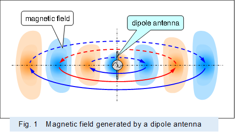
Figure 1 shows schematically a radio wave formed only by a magnetic field, with no electric field. In the figure, orange indicates the magnetic field in the direction from the front to the back of the screen, and blue indicates the magnetic field in the direction from the back to the front of the screen, and the same color scheme is used below to indicate the direction of the magnetic field.
 |
Figures 2 through 4 show schematically how the current supplied to the dipole antenna generates a magnetic field around the antenna while it damps and vanishes in the antenna. Note that the behavior of the electrons is indicated by the simulated circle described in "Form of current".
Figure 2 schematically shows how a balanced signal (alternating current) supplied to the antenna by a pair of conductors passes through the antenna while generating a magnetic field around it and damping gradually.
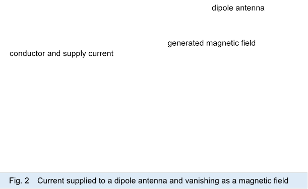

Figure 3A shows schematically how the magnetic field generated around the dipole antenna concentrates in the center of the antenna.
A pair of balanced signals (currents) supplied by the conductors are divided between the upper and lower parts of the dipole antenna, and each current generate a magnetic field of the same polarity around each site. Magnetic fields of the same polarity generated at the upper and lower parts of the antenna are attracted to the center of the antenna by the attractive forces described in "Electrical and Magnetic forces".
The magnetic field attracted to the center then becomes integrated. When the magnetic field is taken from the current going to the end of the antenna and the magnetic field is gathered to the center, the current taken from the magnetic field becomes smaller.
In other words, electrical energy is damped by conversion to magnetic energy, and the vibration amplitude of the electron is smaller.
In "Electrical and Magnetic forces" an example of how current (electric energy) is converted to magnetic energy and becomes smaller is shown how the current through the magnetic core becomes smaller as it magnetizes the magnetic core.
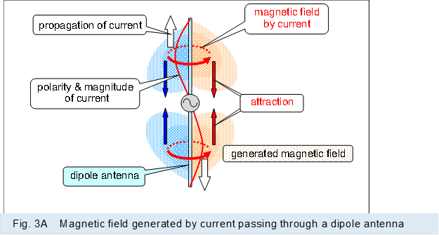 |
Figure 3B shows schematically how the magnetic field generated and integrated around the dipole antenna is separated from the antenna and floats in space.
Magnetic field of different polarity are generated by the subsequent reversed alternating current inside the previously generated and integrated magnetic field. As described in "Electrical and Magnetic forces" the two magnetic fields with reversed polarity have repulsion forces, so the inner magnetic field pushes the magnetic field that gathered and integrated in the center of the dipole antenna.
The magnetic field, which is repulsed and floats in space, travels away from the antenna and flows in the radial direction. The speed of this traveling magnetic field is the light speed.
Note that electrical energy is expended in pushing the outer magnetic field by generating inner magnetic field. The electrical energy is expended by pushing the magnetic field, and the vibration amplitude of the electrons is smaller.
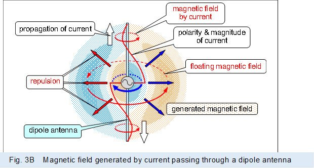 |
Figure 3C shows a magnified view of the current is damped and vanishes as it passes through the dipole antenna, generating the magnetic field around it and pushing the magnetic field in the direction of the radiation.
As described above, the current is damped in the process of passing through the dipole antenna, and vanishes before reaching the end of the antenna, due to the generation of a permanent magnet-like magnetic field and the pushing of it at the speed of light in the direction of the radiation.
In the figure, the sequentially damping of the supplied current, i.e., the decrease in the vibration amplitude of the electrons, is indicated by sequentially smaller simulation circles, and by making the simulation circle at the end of the antenna a point, the current is vanished and the electron is not vibrating.
The simulation circles that do not change in size, indicated by dashed line, are for reference to show the phase of the electrons at each position, and are simulation circles corresponding to current in which the amplitude of the electron vibration does not change, such as the current through a conductor.
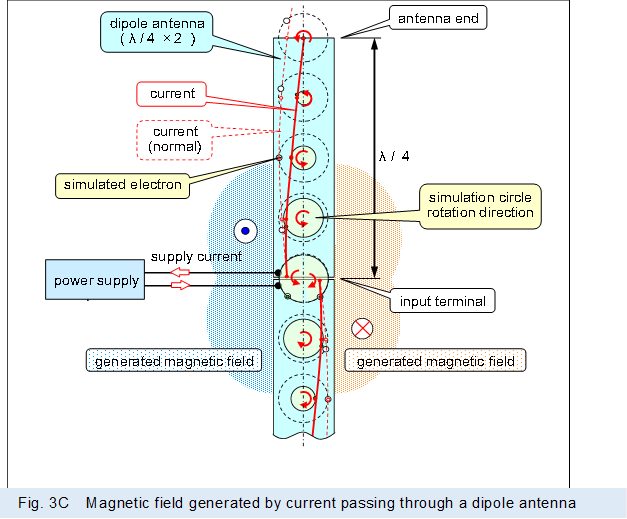 |
Figure 4 shows schematically how the magnetic field generated around the dipole antenna is pushed in the radial direction by a subsequent magnetic field with reversed polarity.
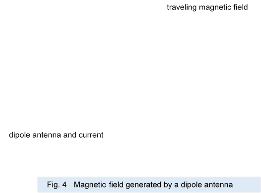

As described above, in a transmitting dipole antenna, a half-cycle of supplied alternating current generate an integrated magnetic field around the antenna, and subsequent half-cycles of current float the previous generated magnetic field in space and push it farther out.
The repeated operation then generates a ring-shaped magnetic field, i.e., a radio wave, that broadens as it flows at the speed of light.
To put energy in perspective, the electrical energy supplied to the antenna is used to generate a magnetic field and to push the previously generated magnetic field farther away, vanishing before it reaches the end of the antenna.
While the electrical energy supplied to the antenna vanishes, a permanent magnet-like magnetic field is generated from the current, and given kinetic energy moving at the speed of light by the current and magnetic energy is output.
In other words, the antenna is a transducer that converts supplied electrical energy into magnetic energy with kinetic energy, like a permanent magnet traveling at the speed of light, and outputs it.
As described above, radio waves are formed by magnetic fields that travel at the speed of light through space.
And if the radio waves are traveling magnetic fields, they can propagate in a vacuum with no medium.
And radio waves have no electric field and no displacement current.
As described above, the current going through the antenna is not reflected at the end of the antenna, because it is vanished before reaching the end of the antenna, while maintaining the form of the traveling wave.
Therefore, there is no resonant action at the antenna and no standing waves are formed at the antenna.
In addition, as described above, the operation of the antenna cannot be explained by a single micro-dipole antenna, because radio waves are formed by the current going through the antenna and the operation of each in each part of the antenna.
If the operation of the antenna is considered by the operation of the micro-dipole antenna, then the operation of multiple micro-dipole antennas must be integrated by using multiple micro-dipole antennas corresponding to the operation of each antenna location.
< 2 Pyramidal horn antenna to generate magnetic field >
Figure 5 shows the magnetic field generated by a pyramidal horn antenna.
 |
The alternating current in the pyramidal horn antenna goes through the center of the inner surface of the flat plate, as shown in "Electrical and Magnetic forces".
Figure 6 shows schematically the path of the current going from the square waveguide to the pyramidal horn antenna and how the current vanishes in the horn.
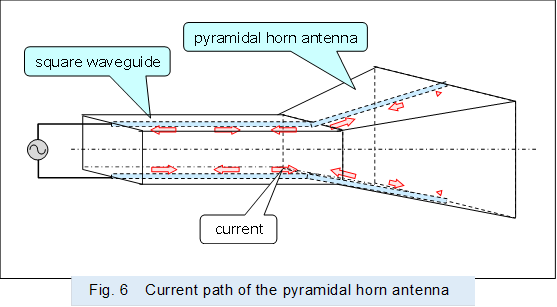 |
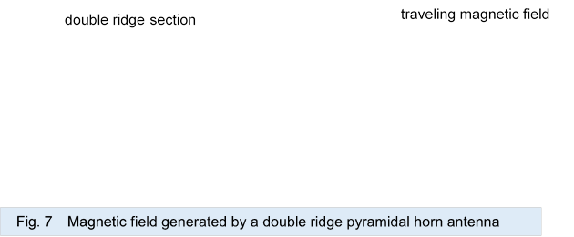
Figure 7 shows the current and the magnetic field generated by the current in a double-ridge pyramidal horn antenna with a well-defined current path by the ridge.
As shown above, the simulated circle is used to represent the behavior of electrons, schematically showing how a ring-shaped magnetic field with the axis of rotation perpendicular to the direction of travel is generated and pushed out of the aperture by a subsequent ring-shaped magnetic field with inverted polarity.
As the current goes through the opposing parts of the upper and lower ridges, each going up and down, the generated ring-shaped magnetic field stays in the center and away from the current due to the attraction it exerts on its own.
In addition, the current taken by the magnetic field is damped and vanishes before it reaches the aperture of the antenna.
On the other hand, the ring-shaped magnetic field that stays in the center and floats in space is pushed out of the aperture by the repulsive force generated by the subsequent ring-shaped magnetic field with reversed polarity.
The speed of the magnetic field pushing out from the aperture and traveling away is light speed.
As described above, in a pyramidal horn antenna, the magnetic field generated by the supplied current floats in space and pushed out from the aperture and travels away by the reversed polarity magnetic field generated by the subsequent current.
The magnetic field generated is the same as a ring-shaped magnetic field with the axis of rotation perpendicular to the direction of travel generated by the dipole antenna.
The pyramidal horn antenna, like the dipole antenna, is a transducer of electrical energy and magnetic energy.
Note that the radio waves generated by the pyramidal horn antenna are also magnetic fields that travel at the speed of light through space in the same form as the dipole antenna, and no electric field or displacement current is required for their production.
.
< 3 Conical horn antenna to generate magnetic field >
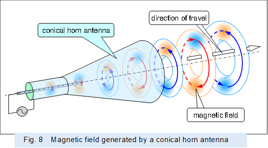
Figure 8 shows the magnetic field generated by a conical horn antenna.
 |
The alternating current in the conical horn antenna goes through the inner surface of the horn uniformly, as shown in "Electrical and Magnetic forces".
Figure 9 shows schematically the path of the current going from the circular waveguide to the conical horn antenna and how the current vanishes in the horn.
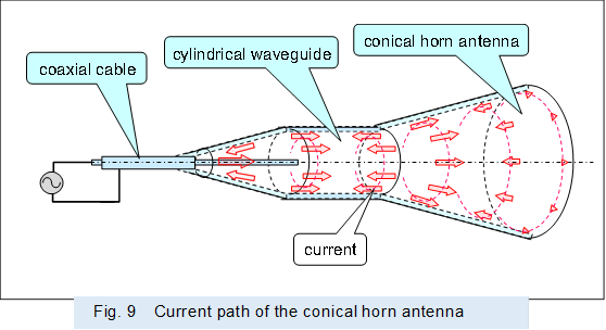 |
Figure 10 shows the current and the magnetic field generated by the current from the coaxial cable to the conical horn antenna.
As shown above, the simulated circle is used to represent the behavior of electrons, schematically showing how a ring-shaped magnetic field with the axis of rotation in the direction of travel is generated and pushed out of the aperture by a subsequent ring-shaped magnetic field with reversed polarity.
As the current goes through the inner wall of the horn and expands in the circumferential direction, the ring-shaped magnetic field generated by the current is shrunk and away from the current due to the attraction it exerts on its own.
In addition, the current taken by the magnetic field is damped and vanishes before it reaches the aperture of the antenna.
On the other hand, the ring-shaped magnetic field that is away from the current and floats in space is pushed out of the aperture by the repulsive force generated by the subsequent ring-shaped magnetic field with reversed polarity.
The speed of the magnetic field pushing out from the aperture and traveling away is light speed.
As described above, in a conical horn antenna, the magnetic field generated by the supplied current floats in space and pushed out from the aperture and travels away by the reversed polarity magnetic field generated by the subsequent current.
The magnetic field generated by the conical horn antenna is ring-shaped with the axis of rotation in the direction of travel, and is the same kind of magnetic field generated by a synchrotron. In other words, the magnetic field generated by a conical horn antenna is the same kind of electromagnetic wave, including light.
The conical horn antenna, like other antennas, is a transducer that converts electrical energy into magnetic energy with kinetic energy, and does not require an electric field or displacement current.
< 4 Loop antenna to generate magnetic field >
Figure 11 shows the alternating current supplied through the conductor to the loop antenna, which is about 1/2 wavelength in diameter.
The magnitude of the current in each part of the loop formed by conductor is indicated by the simulated circle described above in the "Form of current".
Then, as in the description of the dipole antenna above, the simulated circles are sequentially smaller from the supplying side of the loop to the opposite side of the loop.
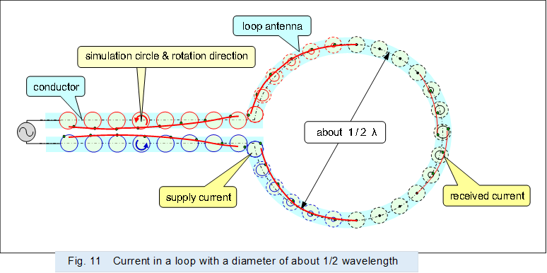 |
The loop antenna with the upper 1/4 loop and the lower 1/4 loop on the supply side connected to the conductor form a pair of dipole antenna, as shown in Figure 11.
Then, like a dipole antenna, it generates a magnetic field that floats in space and pushes the magnetic field around it, thus vanishes the supplied current.
In the figure, the simulated circle indicates a point where is no current.
On the other hand, the semicircle opposite the supply side receives the magnetic field generated by the supply side semicircle and produces a receiving current. It then actuates like a waveguide in a Yagi-Uda antenna.
Thus, the loop antenna has the characteristics of a Yagi-Uda antenna with a single waveguide.
Figure 12 shows the alternating current supplied through the conductor to a very small loop, using simulated circle as shown above.
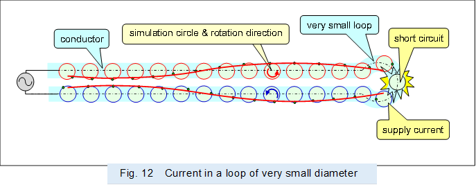 |
If the loop is very small, there is no current damping within it, and there is excessive current, which results in a short-circuit condition. Thus, the supplied power is wasted and does not generate radio waves, which are traveling magnetic fields.
Figure 13 shows the alternating current supplied through the conductor to a loop that is smaller than 1/2 wavelength in diameter, using simulated circle as shown above.
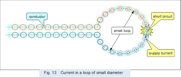 |
If the diameter of the loop is smaller than 1/2 wavelength, the current cannot damp within it, resulting in a nearly short-circuit condition, and there is a big current, which does not generate a sufficient traveling magnetic field, radio waves.
Incidentally, even if the diameter of the loop is smaller than 1/2 wavelength, short-circuits can be prevented by winding the conductor several times around like a coil.
Then, for example, multiple wound transmitting and receiving coils can be placed opposite each other (aligning the central axes of the coils) and applied to coils for power transmission in a non-contact (wireless) power transfer device, using operations such as electromagnetic induction and magnetic resonance.
However, the magnetic field generated by a coil with multiple windings of conductors does not float in space away from the coil; it stays in place and does not travel, so the coil is not an antenna that generates radio waves.
In other words, the magnetic field that is the radio wave in the far field, which travels away from the loop antenna, and the magnetic field in the near field, which does not travel away from the coil, are not the same magnetic field.
Figure 14 shows the alternating current supplied through the conductor to a loop that is larger than 1/2 wavelength in diameter, using simulated circle as shown above.
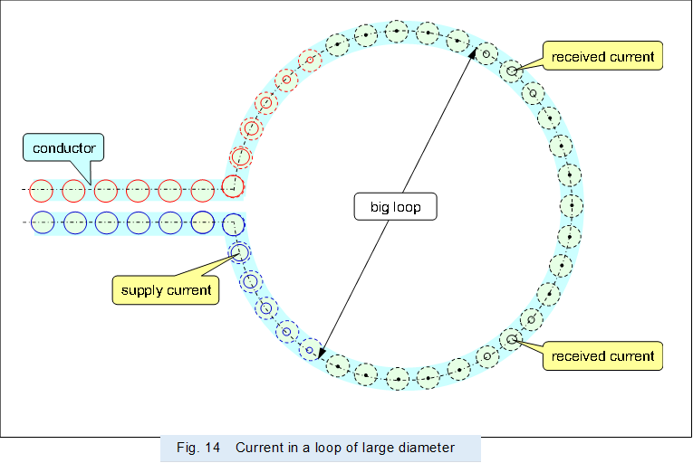 |
If the diameter of the loop is larger than 1/2 wavelength, it is possible to form a dipole antenna with semicircle on the supply side and generate radio waves, which is a traveling magnetic field.
However, unwanted current is produced in the loop (conductor) other than the part that operates as a dipole antenna on the supplying side when it receives the magnetic field (radio wave) generated by the loop on the supplying side. This produced current interferes to the propagation of the magnetic field generated by the loop on the supplying side.
Therefore, inadvertently larger loop diameters will not improve the characteristics.
< 「Electromagnetic waves are traveling magnetic fields」・「Receive electromagnetic waves」 >