Helix World +
Theory of electric and magnetic field in electromagnetic waves
1 Electromagnetic waves have no electric field − 日本語 − <Reference 王様は裸>
2 Unclear about radio waves − 日本語 −
3 Form of current − 日本語 − <Reference Comment>
4 Electrical and Magnetic forces − 日本語 −
5 Electromagnetic waves are traveling magnetic fields − 日本語 −
6 Generate electromagnetic waves − 日本語 −
7 Receive electromagnetic waves − 日本語 −
8 Polarization − 日本語 −
9 Insertion device for synchrotron − 日本語 −
10 Longitudinal and Transverse Waves − 日本語 −
11 Vibration of string − 日本語 −
Jan./25/2024
< 1 Longitudinal wave >
Supplementary information on longitudinal waves of the same type as the current described above. Figures 1 and 2 show traveling waves propagating in a medium of massive solids, liquids and gases, and Figure 3 shows standing waves.
For example, when a loud sound (120 dB) of 1000 Hz propagates in air (composed of nitrogen and oxygen molecules) at a temperature of 20°C, the displacement (amplitude) of the constituent particles is about 11 μm (travel range: about 22 μm).
The wavelength of the sound is 0.34 m, the sound pressure is 28 Pa, and the velocity (flow velocity) of the constituent particles is 68 mm/s.
Therefore, the range of vibration of the constituent particles is small and cannot be drawn on the same scale as the wavelength of longitudinal wave, so a vibration simulation circle is used that largely magnifies the behavior of the constituent particles, as in the description of "Form of current" above.
As mentioned above, the axis perpendicular to the direction of propagation of the vibration/velocity simulation circle indicates the velocity of the constituent particles, with the direction of motion indicated above and below the central axis, and the magnitude of the velocity indicated by the distance from the central axis.
Then, the distribution of the velocity is shown by the solid red lines connecting the velocities of the constituent particles in each part. The distribution of the density (pressure) of the constituent particles is shown by the blue dashed line, with the vibration/density simulation circle indicating the density (pressure) of the constituent particles that share the center with the vibration/velocity simulation circle.
The vibration simulation circle is a circular motion of the reciprocating motion of the constituent particles for convenience, and for the purpose of drawing the distribution of velocity and density (pressure) as a sine wave, the rotation direction of the vibration simulation circle is set to clockwise in the longitudinal wave propagating from left to right on the screen.
Incidentally, in the current described above, the direction of current is in the opposite direction to the direction of electron motion, so in the current from left to right on the screen, the direction of rotation of the vibrating simulated circle is anticlockwise rotation.
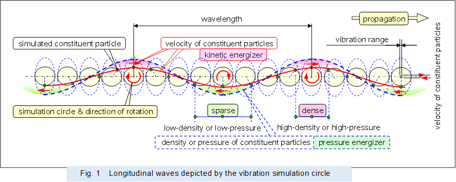 |
Figure 2 shows the traveling longitudinal wave propagating in the medium. In a traveling longitudinal wave, each constituent particle is vibrated by the pressure from the neighboring constituent particles, and the vibrations of the constituent particles are propagated sequentially.
And if there is no damping, each vibration simulation circle is the same shape.
![]()
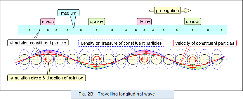 |
Longitudinal waves have kinetic energy due to the moving (with velocity) medium which has mass, and pressure energy due to the density of the medium which has mass.
In a traveling longitudinal wave, kinetic energy and pressure energy propagate in phase at the same time, and both propagate energy in pairs.
Figure 3 shows the standing longitudinal waves generated in the medium. In a standing longitudinal wave, adjacent constituent particles vibrate in synchrony (in phase) due to the pressure they each emit.
The vibration simulation circles in the standing waves are corresponding in size to their respective locations.
![]()
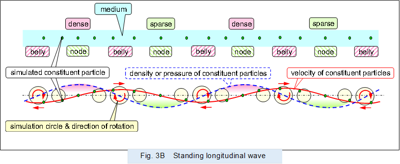 |
In standing longitudinal waves, energy is alternately converted from kinetic energy to pressure energy or from pressure energy to kinetic energy.
In other words, energy is conserved at the site by alternately converting one energy into the other and vice versa.
< 2 Transverse wave >
Supplementary information on transverse waves that are sinusoidally varying, which is different from the current described above. Figure 4 shows a traveling wave propagating on the surface of a solid or liquid with mass, and Figure 5 shows a standing wave.
For example, in a transverse wave formed on the surface of water (the constituent particles are water molecules), each water molecule moves in an ellipse that can be drawn on the same scale as its wavelength (the ratio of the major diameter to the minor diameter varies by situation). The constituent particles of the transverse wave propagating from left to right on the screen rotate clockwise on their own motion circles.
The motion circles shown in Figures 4 and 5 indicate the position of each constituent particle as it vibrates reciprocally in the vertical and horizontal, and the paths of the each constituent particle, unlike the longitudinal wave vibration simulation circles described above, which show the reciprocal vibration and flow velocity of the constituent particles.
Then, a blue dashed line connecting the constituent particles on the motion circle of each part indicates the height of the surface (water surface).
The distribution of the horizontal velocity of the constituent particles is shown by the solid red line, using a vibration simulation circle that shows the horizontal vibration and velocity of the constituent particles that share the center with the motion circle.
Figure 4 shows the traveling transverse wave propagating on the surface of the liquid. In a traveling transverse wave, each constituent particle is vibrated by the pressure from the neighboring constituent particles, and the vibrations of the constituent particles are propagated sequentially.
The motion circle in the traveling wave is an ellipse with its axis in the direction of travel and the direction orthogonal to it, and if there is no damping, each motion circle is the same shape.
Incidentally, the speed at which the internal constituent particles propagate by pressure as longitudinal waves is, for example, the speed of pressure propagation in water, i.e., the speed of sound in water (speed of longitudinal waves) is about 1500 m/s, whereas the speed of transverse waves on the water surface can be followed by the eye.
In other words, the traveling velocity of internal longitudinal waves is very faster than the velocity on surface transverse waves.
Therefore, the transverse wave is a wave that propagates at the height and velocity of the constituent particles, because the density difference due to longitudinal waves can be neglected and the density of the constituent particles is nearly equal.
![]()

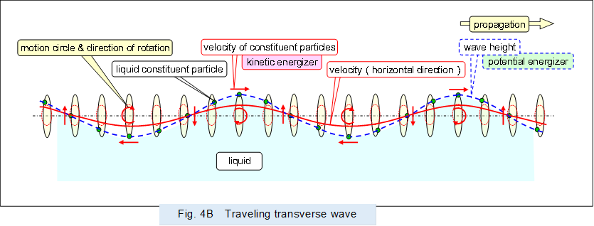 |
Traveling transverse waves on liquid surfaces have kinetic energy due to the moving (with velocity) medium which has mass and potential energy due to the height of the medium which has mass.
In a traveling transverse wave, kinetic energy and potential energy propagate in phase at the same time, and both propagate energy in pairs.
Note
The traveling transverse wave propagating on the surface of a liquid also has kinetic energy when a medium with mass moves up and down, which is vibration energy that alternates with the potential energy due to the height of the medium.
To contrast with the behavior of longitudinal waves, the discussion of the vertical kinetic energy of the medium is omitted in the above.
Figure 5 shows the standing transverse waves generated on the surface of the liquid. In a standing transverse wave, adjacent constituent particles vibrate in synchrony (in phase) due to the pressure they each emit.
The motion circles in the standing waves are elongated ellipses and corresponding in size to their respective locations, and each constituent particle moves in a roughly linear reciprocating motion.
![]()
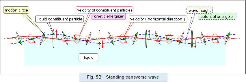 |
In a standing transverse wave on a liquid surface, energy is alternately converted from kinetic energy to potential energy or from potential energy to kinetic energy.
In other words, energy is conserved at the site by alternately converting one energy into the other and vice versa.
Note
The standing transverse wave generated on the surface of a liquid also has kinetic energy when a medium with mass moves up and down, which is vibration energy that alternates with the potential energy due to the height of the medium.
To contrast with the behavior of longitudinal waves, the discussion of the vertical kinetic energy of the medium is omitted in the above.