Helix World +
Theory of electric and magnetic field in electromagnetic waves
1 Electromagnetic waves have no electric field − 日本語 − <Reference 王様は裸>
2 Unclear about radio waves − 日本語 −
3 Form of current − 日本語 − <Reference Comment>
4 Electrical and Magnetic forces − 日本語 −
5 Electromagnetic waves are traveling magnetic fields − 日本語 −
6 Generate electromagnetic waves − 日本語 −
7 Receive electromagnetic waves − 日本語 −
8 Polarization − 日本語 −
9 Insertion device for synchrotron − 日本語 −
10 Longitudinal and Transverse Waves − 日本語 −
11 Vibration of string − 日本語 −
Sept./20/2025
< 1 Unclear about radio waves generated from dipole antennas >
○ Undefined matter 1
As shown in Figure 1, a radio wave generated from a transmitting dipole antenna and propagating through space is illustrated by a concentric magnetic field centered on the antenna and lines of electric force (electric field) surrounding this magnetic field in a loop.
In this figure, the magnetic field from the front to the back of the screen is shown in orange, and the magnetic field from the back to the front of the screen is shown in blue. The same color scheme is used below to indicate the polarity of the magnetic field.
 |
In this description, in the process of generating radio waves, in which loop-shaped lines of electric force are generated one after another and move away from the antenna, the lines of electric force from the positive potential part to the negative potential part of the antenna, shown in the center of Figure 1, expand and become larger in an arc shape when the difference in potential between the two parts increases. It is then description that when the potential difference between the two ends of the antenna decreases, the swollen lines of electric force detached from the antenna and the ends close to form a loop.
In reality, however, the line of electric force shrinks and shortens when the potential difference between the two ends of the antenna decreases, and disappears when the potential difference becomes zero. Therefore, a looped line of electric force is not formed by a dipole antenna.
Incidentally, the vertically polarized radio waves of AM broadcasts transmitted non-directionally around the antenna can be transmitted from a single vertical rod antenna. The transmitted electric field (lines of electric force) can be illustrated and explained as shown in Figure 1. However, horizontally polarized radio waves can only be explained by the combination of a horizontally mounted transmitting antenna and a horizontally mounted receiving antenna positioned opposite it. If one were to deliberately attempt to depict the non-directional horizontal polarization electric field used in FM or TV broadcasting, it might appear as concentric circles centered on the antenna. But such an electric field is impossible.
○ Undefined matter 2
The lines of electric force indicate the presence of an electric field, which has the following properties and is illustrated in Figure 2.
〔 Properties of lines of electric force 〕
・ The direction of the ambient electric field by connecting the positive high potential charge point (starting point) and the negative low potential charge point (ending point).
・ On the line connecting two points of potential difference, the potential changes continuously and is orthogonal to the equipotential line.
(For example, in Figure 2, there is a potential difference between points A1 and A2 on one line of electric force, and points A1 and B and points C1 and C2 facing each other on parallel lines of electric force have the same potential.)
 |
Figure 3 is an extracted cutout of a portion of the looped lines of electric force shown in Figure 1.
 |
In the looped line of electric force passing through points A1 and A2 in this figure, there is no potential difference between points A1 and A2 because the loop has no start point and no end point.
In each looped line of electric force through points A1 or B, the two lines of electric force through points A1 and B are parallel, so there is no potential difference between them as well.
Similarly, there is no potential difference between points C and A1 of adjacent and parallel looped lines of electric force.
After all, there is no potential difference between points A1, A2, B and C, The looped lines drawn in Figure 1 to indicate the electric field have no meaning, and there is no potential difference in the space shown in Figure 1.
Therefore, there is no electric field in this space, and there is no electric field in radio waves.
○ Undefined matter 3
The existence of an electric charge is essential for the starting and ending points of the lines of electric force, as shown in Figure 2.
Therefore, if the existence of an electric field is essential, radio waves cannot propagate in a vacuum because there are no lines of electric force in an empty vacuum (no matter with an electric charge).
Initially, ether, which also exists in a vacuum, was considered as a medium for propagating radio waves, but its existence has been denied.
○ Undefined matter 4
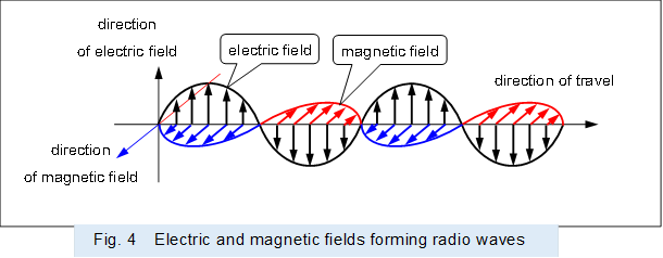
As shown in Figure 4, some illustrate the radio waves generated by a transmitting dipole antenna and propagating through space by means of electric and magnetic fields drawn in a sinusoidal transverse wave.
However, voltage is a convenient indicator of the difference in density of electrons in a conductor. Similarly, an electric field is an indicator of the difference in density of electrons in a field in which electrons exist, and that indicator has no substance.
Therefore, there is no movement or oscillation in an insubstantial electric field, and the electric field in a radio wave does not form a transverse wave..
 |
○ Undefined matter 5
As shown in Figure 5, some illustrate the radio waves generated by a transmitting dipole antenna and propagating through space using displacement currents, which are virtual currents generated by fluctuations in the electric field.
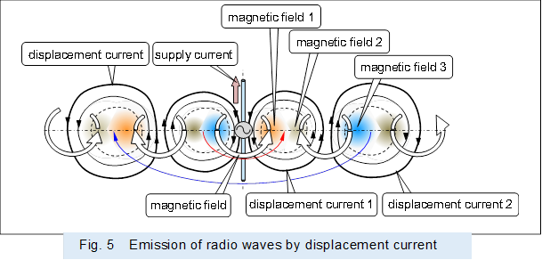 |
In Figure 5, first, a magnetic field 1 is generated around the antenna by the current supplied to the antenna.
Next, displacement current 1 flows to cancel out magnetic field 1, and magnetic field 2 is generated to cancel out displacement current 1.
Next, displacement current 2 flows to cancel out magnetic field 2, and magnetic field 3 is generated to cancel out displacement current 2.
It is explained below that radio waves are propagated by alternately generating displacement current and magnetic field.
However, the magnetic field 1 generated by the antenna is a ring centered on the antenna, as shown in the upper diagram in Figure 6.
Therefore, the displacement current 1 that cancels all of this magnetic field 1 is generated to cover the outside of the magnetic field 1, like a current in a toroidal coil.
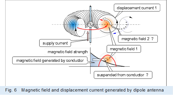
Therefore, if a magnetic field 2 against the displacement current 1 is generated, it will be generated inside the displacement current 1, overlapping the magnetic field 1, as shown in the upper figure of Figure 5.
At this time, the magnetic field 2 cannot leach out through the wall of the displacement current because the displacement current flows without gaps like a wall, Magnetic field 2, which is independent from magnetic field 1 and leaks outside of displacement current 1, is not generated, as shown in Figure 4.
Even if the magnetic field leaches through the wall of the displacement current and generates a magnetic field 2, the magnetic field 3 will be in the form of a ring centered on the antenna shown by the blue line. Therefore, the independent magnetic field 2 and the displacement current do not propagate in a chain-like connection in one direction.
In the first place, the initial displacement current 1 is the current that cancels the magnetic field 1 by generating a magnetic field, and there is no excess current to generate a magnetic field 2, only the excess current required to cancel the magnetic field 1.
In any case, the magnetic and displacement currents do not alternate and cease to occur, so the magnetic and electric fields do not propagate in pairs.
○ Undefined matter 6
As shown in the upper part of Figure 5, there is a magnetic field 1 generated by a transmitting dipole antenna that is drawn and illustrated away from the antenna and floating in space.
Normally, the magnetic field generated by the current flowing in the conductor (antenna) is strongest at the area in contact with the conductor, as shown in the figure below in Figure 5, and there is no gap between the conductor and the antenna, so the magnetic field does not float in space away from the antenna.
However, in radio waves, the magnetic field floats in space and away from the antenna.
The displacement current shown in the figure cannot be interrupted and pull the magnetic field 1 away from the antenna. Therefore, it is necessary to rethink the generation and behavior of the magnetic field, which has been obscured until now.
○ Undefined matter 7
Some explain that a standing wave is formed in the transmitting dipole antenna due to the supplied power, and that radio waves are generated from the standing wave.
However, if a standing wave is formed in the antenna, there is no electrical energy (radio waves) output from the antenna because all electrical energy (power) supplied to the antenna is conserved in the antenna due to the resonant action of the standing wave.
Therefore, it is difficult to believe that standing waves are formed at the antenna, It is necessary to rethink the reason why the supplied power (electrical energy) is converted into radio waves (electric and magnetic field energy), which has been obscured until now.
○ Undefined matter 8
Some explain that a standing wave is formed in the transmitting dipole antenna due to the supplied power, and that radio waves are generated from the standing wave.
If radio waves are generated from standing waves, then by the degree of resonance of the signal supplied to the antenna will decrease the correlation between the magnitude of the supplied signal and the field strength of the output.
Therefore, if the supplied signal is AM modulated signal is transmitted, the field strength will change due to resonance. If it is received and AM demodulated, only a signal of degraded quality, different from the original signal, can be obtained.
Also, if an FM modulated signal is transmitted, the degree of resonance will change depending on the modulated frequency, The output field strength will change, and an AM component will be superimposed on the radio wave, When it is received and FM demodulated, the AM component becomes noise and only a signal of degraded quality can be obtained.
If digital signals modulated by Amplitude Shift Keying (ASK) or Frequency Shift Keying (FSK) are transmitted, the resonance operation will follow the frequency corresponding to the changing digital signal, causing a delay. The quality of the digital signal, which should be a square wave, is then degraded. As a result, it becomes difficult to transmit digital signals at high speed or density by radio waves. And, if it is a Phase Shift Keying (PSK) modulation, it cannot even generate a radio wave corresponding to a digital signal. Because the resonant operation is stopped by the phase change when the digital signal is changed.
In reality, however, radio and television broadcasts are transmitted without problems, as radio waves corresponding to the signals supplied to the antenna are generated and the signals are not deformed. Digital signals for communication are also transmitted without any problems. Therefore, it is difficult to understand that standing waves are formed at the antenna.
○ Undefined matter 9
The radio waves generated by a transmitting dipole antenna and propagating through space are illustrated by sinusoidal electric and magnetic fields as shown in Figure 4.
As shown in this figure, the major trend is to consider the electric and magnetic fields as transverse waves in phase with each other, orthogonal to each other, as shown in Figure 5, it is a minor school of thought to consider the electric field or displacement current and the magnetic field to be out of phase with each other.
However, the former does not produce the interaction of an electric field with a magnetic field or a magnetic field with an electric field, The latter, in which the electric and magnetic fields are out of phase, is used to explain the interaction necessary for the formation of radio waves.
Also, if we consider that radio waves are generated from standing waves formed in antennas, the phases of potential and current (electric and magnetic fields) are out of phase as in the latter case.
After all, it is ambiguous whether the phases of the electric and magnetic fields are in phase or out of phase.
○ Undefined matter 10
Some consider radio waves by breaking down a dipole antenna into multiple micro-antennas and synthesizing the electric and magnetic fields generated by each of the small antennas. In this consideration, the standing waves are similar to the dipole antenna in which they are formed, and their behavior is represented by the small antennas that operate in phase with the dipole antenna.
However, since the formation of standing waves at the antenna is doubtful as described above, it is necessary to reconsider the idea that radio waves are generated by the traveling waves supplied to the antenna. This requires a new way of thinking, since each part of the antenna will operate differently at different positions and at different times in response to the sequentially traveling waves.
○ Undefined matter 11
A conductive antenna may be used to detect electric fields in radio waves.
However, the signal output from the antenna after detecting a radio wave includes an electric current generated by electromagnetic induction of the magnetic field in the radio wave.
Therefore, it is impossible to determine whether what is detected is an electric field or a magnetic field.
In other words, experiments such as Dr. Hertz's experiment, in which a conductive antenna is used, cannot prove the existence of an electric field in radio waves.
○ Undefined matter 12
Natural light is considered to be a combination of many electromagnetic waves of the same magnitude that are uniformly distributed in the direction of polarization. Because natural light can be decomposed into light polarized in any direction by rotating a polarization filter.
However, the mechanism for aligning the sizes of many electromagnetic waves and distributing them uniformly in the direction of polarization is unclear.
○ Undefined matter 13
It is not yet clear why light, a type of electromagnetic wave, has both wave and particle properties.
It is also not yet clear what a photon is.
< 2 Unclear about radio waves generated from conical horn antennas >
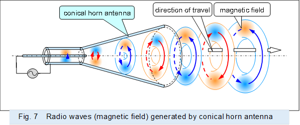
The radio waves generated by the conical horn antenna are ring-shaped magnetic field that travels in the direction of the extension of the antenna's central axis, as shown in Figure 7.
However, there are no documents that suggest this ring-shaped magnetic field as a form of radio waves.
There is also no suggestion of an electric field (lines of electric force) or displacement current corresponding to this ring-shaped magnetic field.
 |
In some descriptions of conical horn antennas, a transducer is inserted between the feed line and the conical horn antenna. The transducer then converts the radio waves to the same form as the conical horn antenna or dipole antenna.
The ring-shaped magnetic field is not recognized, so it seems that they do not dare to generate it and do not think about the existence of the ring-shaped magnetic field.
< 3 Unclear about light and radio waves generated from synchrotrons >
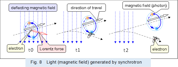
In the synchrotron, synchrotron radiation is generated as shown in Figure 8.
Synchrotron radiation is produced when the direction of travel of an electron moving at the speed of light is bent by an orthogonal deflection magnetic field.
If we think in terms of electrons and magnetic fields, the magnetic field generated around the electrons is separated and straightened by the deflecting magnetic field to form a ring.
However, this synchrotron light, as the name implies, is recognized as light, but is rarely recognized as radio waves. And there is no data to suggest that the ring-shaped magnetic field is light, a form of electromagnetic (radio) wave.
There is also no suggestion of an electric field (lines of electric force) or displacement current corresponding to the above ring-shaped magnetic field.
 |
Note that synchrotron radiation is a suitable material for considering light and radio waves to be the same electromagnetic wave.
< 「Electromagnetic waves have no electric field」・「Form of current」 >