Helix World +
Theory of electric and magnetic field in electromagnetic waves
1 Electromagnetic waves have no electric field − 日本語 − <Reference 王様は裸>
2 Unclear about radio waves − 日本語 −
3 Form of current − 日本語 − <Reference Comment>
4 Electrical and Magnetic forces − 日本語 −
5 Electromagnetic waves are traveling magnetic fields − 日本語 −
6 Generate electromagnetic waves − 日本語 −
7 Receive electromagnetic waves − 日本語 −
8 Polarization − 日本語 −
9 Insertion device for synchrotron − 日本語 −
10 Longitudinal and Transverse Waves − 日本語 −
11 Vibration of string − 日本語 −
Sept./20/2025
< 1 Dipole antenna to receive magnetic field >
As shown in Figure 1, when the approaching (traveling) alternating magnetic field (radio wave) crosses a rod antenna or dipole antenna, which is a rod-shaped (wire-shaped) conductor, an electromotive force is produced a current in the antenna, and the current corresponding to the traveling magnetic field is output from the output section.
In the figure, orange indicates the magnetic field in the direction from the front to the back of the screen, and blue indicates the magnetic field in the direction from the back to the front of the screen, and the same color scheme is used below to indicate the direction of the magnetic field.
![]()
 |
Figure 1C shows how the traveling magnetic field (alternating magnetic field) vibrates the electrons in the antenna when it crosses the dipole antenna, induce a current, using the simulated circle described in "Form of current".
Each electron in the antenna receives vibrations from adjacent electrons by proximity effect (current flows). And each electron receives vibrations (current is induced) at the same timing and with the same magnitude force due to the Lorentz force exerted by the traveling magnetic field. The phase of the vibrating electrons (current phase) is shown by the simulated electrons on the simulated circle indicated by the dashed-line in the figure. The sequential increase in the amplitude of each electron's vibration to the output terminal— in other words, the increase in current—is shown by enlarging the size of the solid-line simulated circle.
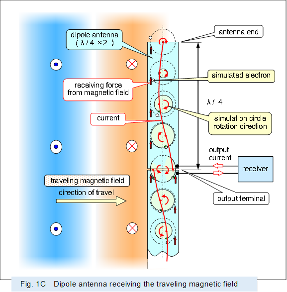 |
Figure 1D is a table roughly showing the current distribution in the antenna (rod-shaped conductor) depicted in Figure 1C.
The current flowing through each part of the conductor, divided into lengths of 1/32 wavelength of the magnetic field, was calculated while varying the crossing magnetic field (received radio waves) every 1/16 cycle. It shows how the current induced at each part propagates sequentially.
Note that there is a correlation between the magnitude of the crossing magnetic field and the magnitude of the induced current; the induced current corresponds to the magnitude of the crossing magnetic field.
However, for convenience in this figure, the numerical value indicating the magnitude of the induced current is shown as the same as the numerical value indicating the magnitude of the magnetic field.
Of course, by subdividing the section of the conductor carrying current, subdividing the magnetic field's cycle, and using a corresponding current for the magnetic field, it is possible to show a realistic appearance (where the current flowing through each part of the conductor becomes a corresponding sinusoidal wave). However, even with this level of coarseness, it is possible to explain the behavior of the current flowing in the antenna.
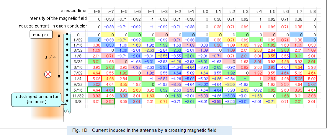 |
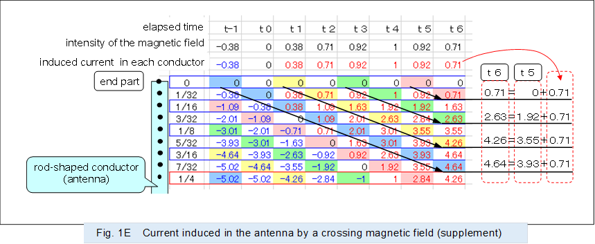
Figure 1E is a supplementary figure to Figure 1D, showing that the current flowing through each part is the sum of the current flowing through the immediately preceding part and the current induced by the magnetic field at that time. For example, the current 4.64 flowing through the conductor part at the 7/32 wavelength timing t6 is the sum of the current 3.93 flowing through the conductor part at the 3/16 wavelength timing t5 and the 0.71 induced at timing t6. It is the total sum of currents induced by the magnetic field at each timing from t-1 to t6.
 |
As shown in the figure above, the current induced by the traveling magnetic field (alternating magnetic field) flows through the antenna at the velocity of light, adding the current induced by each successive magnetic field.
The current reaches its maximum (e.g., ±5.02) at the point where the conductor length is 1/4 wavelength, and decreases beyond this 1/4 wavelength point.
Note that since the velocity of the current flowing through the conductor is slower than the velocity of the magnetic field propagating through space, the current in reality reaches its maximum at a point shorter than 1/4 of the magnetic field's wavelength. This ratio between the current's velocity and the magnetic field's velocity is an element of the antenna's shortening factor.
Incidentally, from the diagram above, one might infer that no current flows when the conductor length is 1/2 the magnetic field wavelength. However, in reality, the conductors forming the antenna have electrical losses. Therefore, the current propagating from the tip, which has decayed along the way, is added to the new current induced by the magnetic field. So, a corresponding current flows even in a conductor of 1/2 wavelength length.
The conductor length equal to 1/4 of the wavelength of the received magnetic field does resemble the length forming a standing wave. However, the behavior of electrons in the antenna is that of a traveling wave, as described in "Form of current" and differs from a standing wave. In other words, the antenna length is not set to resonate the current induced by the received radio waves.
Furthermore, as described above, since the current is output by the traveling magnetic field (alternating magnetic field), even if a rod antenna receives radio waves and outputs a current, this cannot prove that the radio waves have an electric field.
< 2 Loop antenna to receive magnetic field >
When an approaching (traveling) alternating magnetic field (radio wave) crosses a loop antenna composed of conductors, an electromotive force is produced a current in the antenna, and the current corresponding to the traveling magnetic field is output from the output section.
As shown in Figure 2, in a loop antenna which diameter is about 1/2 wavelength of the received alternating magnetic field, the semicircle on the output side operates like the above dipole antenna and outputs a current.
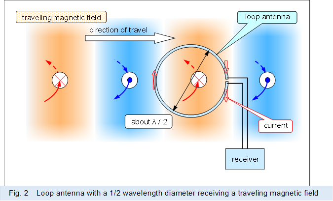 |
In the above loop antenna with a 1/2 wavelength diameter, the semicircle on the opposite side of the output side also produces a current like a dipole antenna and operates like a waveguide for the alternating magnetic field to be received, because this opposite side semicircle is about 1/2 wavelength away from the output side.
Thus, the 1/2 wavelength loop antenna has the characteristics of a Yagi-Uda antenna with a single waveguide.
As shown in Figure 3, in a loop antenna which diameter is smaller than 1/2 wavelength of the alternating magnetic field to be received, this antenna operates like a coil through which the alternating magnetic field penetrates, because each part of the loop is received a magnetic field of the same phase.
In other words, in a loop antenna which diameter is smaller than 1/2 wavelength of the alternating magnetic field, a current is output that against changes in the penetrating magnetic field by electromagnetic induction operation or magnetic resonance operation, like a coil.
 |
When the aperture is small relative to the wavelength of the alternating magnetic field to be received, as in the loop or coil in Figure 3, the magnetic field that penetrates is small and a big output cannot be produced. In many cases, the aperture area is made as large as possible, as in the spider coil or basket coil, where the conductor is wound around multiple times for exclusive receiver use.
In addition, in many cases, a core that collects the magnetic field is inserted, like a bar antenna.
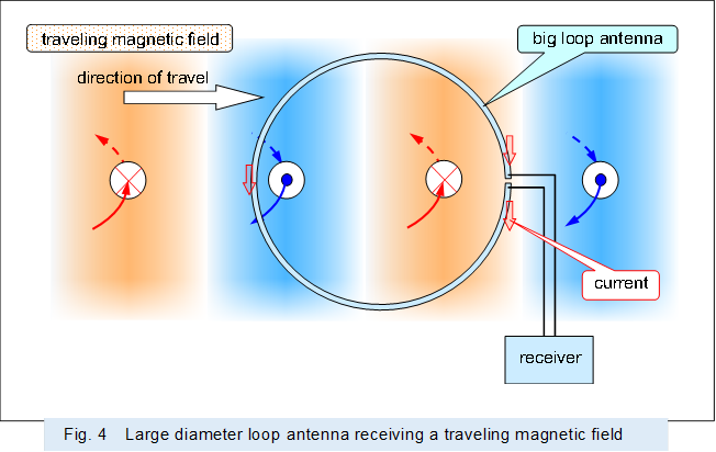
As shown in Figure 4, even in a loop antenna which diameter is larger than 1/2 wavelength of the received alternating magnetic field, the semicircle on the output side operates like a dipole antenna and outputs a current.
However, it receives magnetic fields other than the semicircle on the output side, and the current produced there is not resonant as in the 1/2 wavelength loop antenna above, which inhibits the production of output current and cannot output sufficient current.
 |
Incidentally, the ring-shaped conductor that Dr. Hertz used to prove the existence of radio waves is small relative to the wavelength of the transmitted radio waves, and should be considered a receiving coil rather than a loop antenna.
Thus, as above, even if a ring-shaped conductor receives a radio waves, it cannot claim that the radio waves are formed by an electric field.
< 3 Effect of magnetic field >
As shown in Figure 5, when a metal plate (conductor) is placed in a traveling magnetic field (alternating magnetic field), the magnetic field pushes the metal plate in the direction the magnetic field is traveling. Because eddy currents are produced in the metal plate to obstruct changes in the magnetic field and Lorentz force is produced between the eddy currents and the magnetic field.
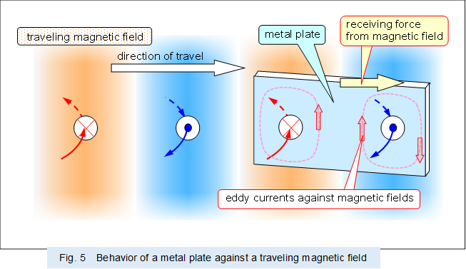 |
The above behavior is the same as that of an AC motor which rotates a rotor or a linear motor which moves in a straight line.
As shown in Figure 6, when an object with a polarized part is placed in a traveling magnetic field (alternating magnetic field), the polarized part to vibrate in each direction. Because the Lorentz force due to the traveling magnetic field actuates the part polarized to a positive or negative potential.
 |
For reference, an ordinary microwave oven use a radio wave (traveling magnetic field) at 2.45 GHz to vibrate the water molecules and heat the water.
As described above, electromagnetic waves (traveling magnetic fields) including radio waves and light have kinetic energy even if they have no mass. Because magnetic fields traveling at the speed of light exert a force on objects.
And what replaces mass in electromagnetic waves (traveling magnetic fields), including radio waves and light, is the intensity of the magnetic field.