Helix World +
Theory of electric and magnetic field in electromagnetic waves
1 Electromagnetic waves have no electric field − 日本語 − <Reference 王様は裸>
2 Unclear about radio waves − 日本語 −
3 Form of current − 日本語 − <Reference Comment>
4 Electrical and Magnetic forces − 日本語 −
5 Electromagnetic waves are traveling magnetic fields − 日本語 −
6 Generate electromagnetic waves − 日本語 −
7 Receive electromagnetic waves − 日本語 −
8 Polarization − 日本語 −
9 Insertion device for synchrotron − 日本語 −
10 Longitudinal and Transverse Waves − 日本語 −
11 Vibration of string − 日本語 −
Sept./20/2025
< 1 Rotated magnetic field >
Figure 1 shows the magnetic field generated by a vertical dipole antenna, shown by an equivalent magnet which is shown in "Electromagnetic waves are traveling magnetic fields", far from the antenna and where the magnetic field is nearly uniform.
![]()
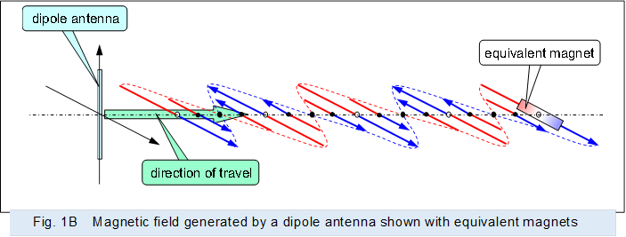 |
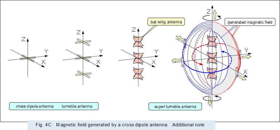
Figure 2 shows a cross dipole antenna in which a horizontal dipole antenna is added to the above vertical dipole antenna, and a 1/4 wavelength delayed signal is supplied to the horizontal dipole antenna.
The configuration of the cross dipole antenna is the same as the stator of a 2-phase AC motor, which generates a rotating magnetic field by orthogonally arranging 2 coils. Note that, as shown in the figure, it is easy to understand if a conductor shown by a dashed line is added to the end of each dipole antenna to make it like a coil.
Therefore, a rotating magnetic field like that generated by an AC motor is generated in the vicinity of the 2 dipole antennas that constitute the cross dipole antenna.
Then, as mentioned above, subsequent alternating signals supplied in sequence make the generated magnetic field independent from the antennas and push away from the antennas. And, while rotating, a rotating magnetic field is generated that travels at the speed of light in the direction perpendicular to the plane formed by the 2 dipole antennas.
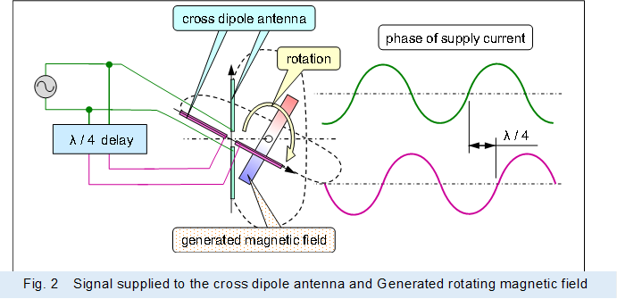 |
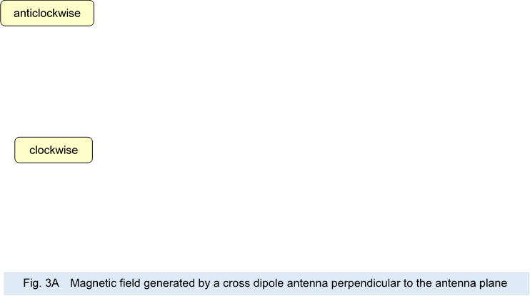
Figure 3 shows the rotating magnetic field generated by the cross dipole antenna. The upper magnetic field is the rotating anticlockwise toward the direction of travel with the output delayed by anticlockwise, and the lower magnetic field is the rotating clockwise with the output delayed by clockwise.
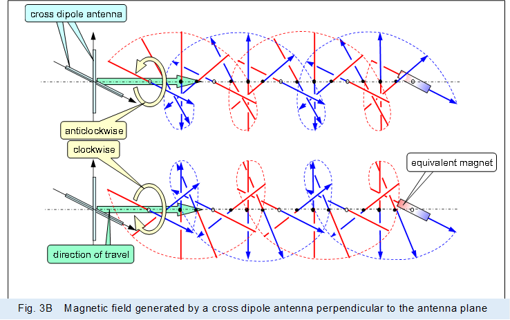 |
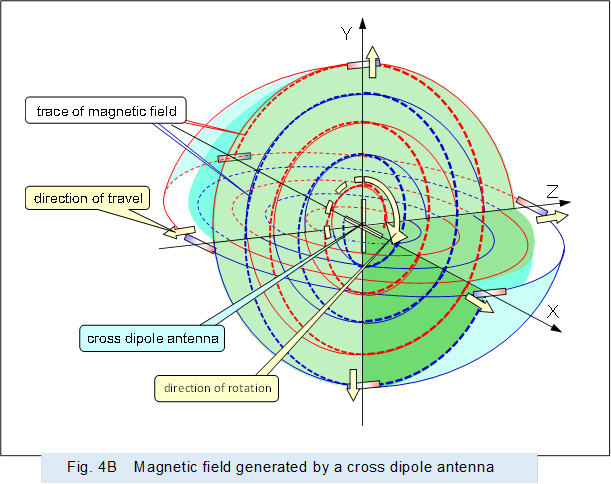
Figure 4 shows the magnetic field generated by the cross dipole antenna in the surroundings.
The magnetic fields traveling in the Z-axis direction rotate about the Z-axis axis as described above. And the magnetic fields traveling in the X-axis and Y-axis directions spread radially, like the magnetic fields generated by a dipole antenna, for each. Note that the direction of the magnetic field spread in the X-axes and Y-axes is orthogonal to the magnetic field generated by the dipole antenna, which is radially spread with the antenna as the central axis.
![]()
 |
Rotating the composition shown in Figure 4B and orienting the Z-axis vertically as shown in Figure 4C configures a turnstile antenna or a super turnstile antenna.
This antenna transmits non-directional radio waves that spread uniformly around the Z-axis while concentrating in the XY plane direction. It is used for antennas for FM and TV broadcasting, etc.
 |
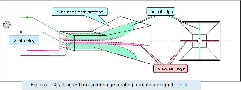
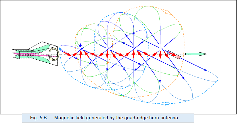
For example, to concentrate the rotating magnetic field in the Z-axis direction, a quad-ridged horn antenna with four ridges is used, as shown in Figure 5A. Then, a 1/4 wavelength delayed signal is supplied to one of the double ridges to generate a rotating magnetic field. Figure 5B shows the rotating magnetic field generated by the quad-ridge horn antenna in Figure 5A.
 |
|||
 |
|||
In AC motors for power use, multiple coils and a multi-phase power supply are used to distribute the current so that the current in each coil is not excessive. In antennas that generate powerful magnetic fields, the number of ridges may be further increased.
Incidentally, the above mentioned "Receive electromagnetic waves" indicates that the traveling magnetic field has a force that pushes a conductive object. In addition to the force pushing the conductive object, the magnetic field traveling while rotating has the force to rotate the conductive object like an AC motor.
< 2 Twisted magnetic field >
Figure 6 shows the ring-shaped magnetic field generated by the conical horn antenna described above.
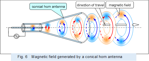 |
Figure 7 shows the schematic configuration of a mode converter that is a spiral cut through the end of a conical horn antenna which is provided in a gyrotron. And it shows how the ring-shaped magnetic field input from the cylindrical waveguide is converted by this converters into a coil-shaped twisted magnetic field.
![]()
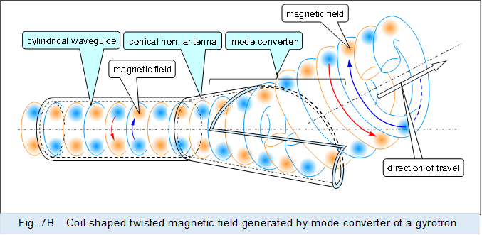 |
As described above, when a ring-shaped magnetic field input from a cylindrical waveguide passes through a spirally cut mode converter, whereas the magnetic field on the wall side of the converter travels along the wall, whereas the magnetic field generated from the cut section of the converter expands in the direction away from the axis of the waveguide (converter)..
When the ring-shaped magnetic field is pushed through the mode converter by subsequent magnetic fields, and expands as it progresses, the magnetic path of each ring-shaped magnetic field is biased to one side and extended.
At some time, the magnetic path length that are coiled by disconnecting each ring and connecting the magnetic paths adjacent to each in series becomes shorter than the total length of the magnetic paths of each ring in parallel and connected in series. After that, in order to continue the shorter magnetic path, which is the stable side, the ring-shaped magnetic paths are sequentially disconnected and connected in series to form a coil-shaped twisted magnetic field.
Then, coil-shaped twisted magnetic field is extended in a direction away from the axial direction of the waveguide (converter). In other words, a coil-shaped twisted magnetic field is output from the mode converter.
Note that in ordinary gyrotron documents, the outer cylinder of the cavity resonator of the gyrotron corresponds to the cylindrical waveguide of Figure 7. The coil-shaped twisted magnetic field output from the mode converter is called a high-frequency beam, and has a sharp directivity like light (Gaussian beam).
Incidentally, the above coil-shaped twisted magnetic field can also be formed by a cylindrical mode converter in the middle of a cylindrical waveguide, as shown in Figure 8.
This cylindrical mode converter is made by cutting a portion of the wall of a cylinder connected to a cylindrical waveguide in the axial direction. And, the wall is stretched in the circumferential direction so that the path lengths of the areas through which the current path become sequentially longer, and the wall is bulged out in an unbalanced shape. Then, the difference in path length between the shortest and longest parts of the current path is made to correspond to one wavelength of the passing alternating current signal.
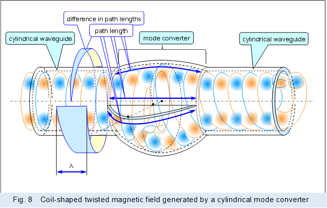 |
In the above cylindrical mode converter, the current producing a ring-shaped magnetic field input from the left cylindrical waveguide is converted to a current producing a coil-shaped twisted magnetic field, which is output to the right cylindrical waveguide.
When generating an inverted magnetic field with the twisting direction reversed, a cylindrical mode converter which reverses the direction of rotation to extend the path length is used.
However, the resulting cylindrical mode converter with the twist direction reversed is the same as the original cylindrical mode converter with the input and output sides switched.
In order to receive the coil-shaped twisted magnetic field and return it to a ring-shaped magnetic field, a cylindrical mode converter with the twisting direction reversed is used, but the same one can be diverted as described above.
Incidentally, optical experts seem to refer to the light formed by the ring-shaped magnetic field in Figure 6 above as normal light, and the light formed by the coil-shaped twisted magnetic field in Figure 7 as an optical vortex.
< 「Receive electromagnetic waves」・「Insertion device for synchrotron」 >